Wednesday, March 27, 2013

Cheap Online Digital Microscope

A USB digital microscope that I bought from www.dx.com turned up today.  I wanted something cheap to inspect soldering and PCBs, and at $30 dollars I didn't have much to lose.

Product Box
USB Microscope
The specs say the sensor is 2.0 Mega Pixels, but I can't get anything above 480x640.  Might be a driver issue, but as the included CD was blank and there is no website to download drivers the from, I'm stuck with it.  Doesn't worry me, I was fully expecting problems.  480x640 is fine for my purposes.

Product Box
Microscope Specs

Product Contents
Package Contents

To focus the scope you manually turn a small black wheel on the side of the case.  There is also a button on the camera to take snapshots, which doesn't work.  I assume it would work if had the right drivers, but I prefer to trigger the snapshot from the computer.  This eliminates any movement of the camera that may blur the picture.  The on-off switch controls a ring 8 LEDs around the lens that are used to illuminate the subject.

It comes with a stand that is pretty much useless, which is what I had expected from reviews of similar products.

USB Microscope
Microscope with stand

There isn't much to say, it does what I want and I'm happy with it.  As expected the product isn't great, but it gets me the results I want at a price that I'm happy to pay.

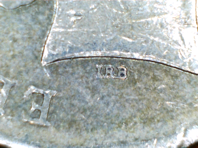
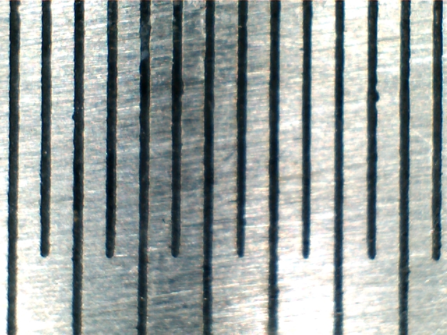
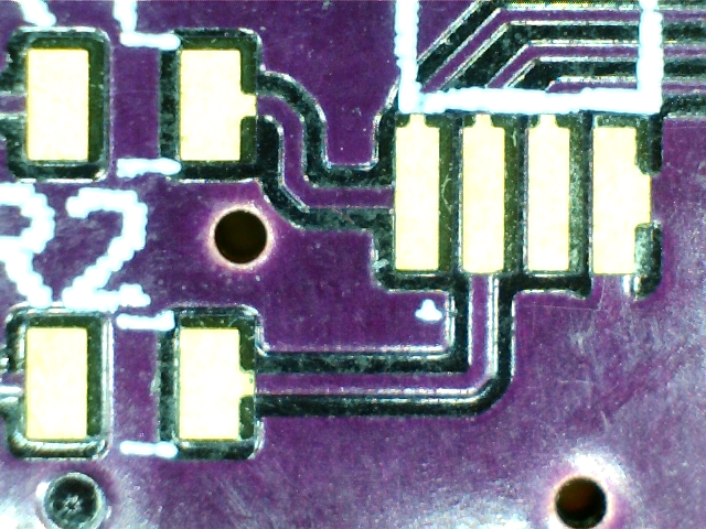
A few sample shots are shown below to get an idea of the results.  Using a ruler as a test shot I was able to determine that there are about 100 pixels per mm or 2.5 pixels per mil which agrees with the track sizing on a couple of the PCBs imaged.

It also looks as if the images are a little over exposed.  I may have to perform some adjustments there.

Surface Mount Resistor

Five Dollar Note
Australian Five Dollar Note

2 dollar coin
Back of Australian 2 dollar coin

Steel Ruler
Metal Ruler with 0.5 mm Markings

PCB
Soldermask, Track, and Pads

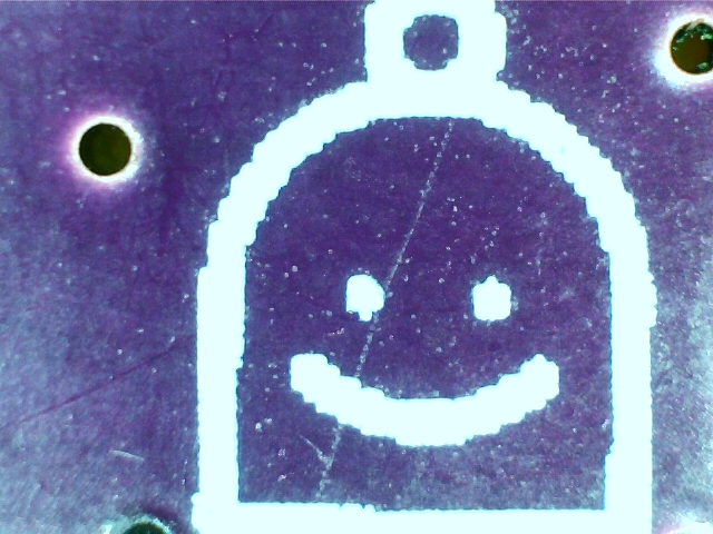
PCB
Silkscreen

PCB
Silkscreen

Saturday, March 16, 2013

Manual vacuum Pick-up Tool Attempt 1

The latest project I've been working on has been an absolute nightmare.  I've been trying to create a small manual vacuum pick-up tool for electronics work.  I have the pump and tubing all sorted, I have the tips used to pick up the parts, all I need now is a way to connect them all.

Below is the basic idea of what I'm trying to accomplish.  I have a small rubber vacuum tip from a cheap tool I bought on-line pushed onto the end of an angled dispensing tip.  The dispensing tip has a luer taper connection that needs to connect to a pen like hand held tool.

Threaded Luer Adapter
Manual vacuum pick-up tool tip

The reason I chose this design is that I can easily change tips depending on the size of the part I need to handle.  With the rubber suction tip in the image above, I can easily pick up a PCB 0.5 x 0.75 inches.  By changing the tip to something smaller like in the image below, I've been able to pick up 0603 resistors easily.  This method makes the tool reasonably flexible.

Threaded Luer Adapter
Smaller dispensing tip

As I'm unsure of what size tips I'll need, I bought a kit that has a selection of them.  Yeah, it's more expensive than buying them off a place like eBay, but once I know what sizes I'll need, I can then buy cheaper batches, but in theory I wont need too many of them.

Dispensing Tips
Range of dispensing tips

Seems easy right.  Wrong.  Adapters for luer lock connections aren't that easy to come by.  You don't just go to the local hardware and buy one.  I figured the easiest way to get one was buy it from the same supplier that sold me the dispensing tips.  I choose the black fitting you can see in the image above.  It's a 1/4 inch NPT thread to a male luer lock connector.  I however didn't understand that an 1/4 inch NPT thread is actually about 1/2 an inch across.  This means that once a pipe had a thread cut in it and attached, the outside diameter of the pipe would be around 20mm in diameter, which is a little too big.  "Easy I'll just glue a plastic pipe inside the fitting" i thought.  Wrong, the fitting is polypropylene, which is super-glue resistant, which meant I had to track down a heptane primer for the plastic before applying super-glue.  Finding a suitable piece of plastic pipe wasn't easy but in a pinch you make do.

Pen case
Plastic pipe from a pen case

Luckily I decided to tackle the fitting on the other end before attaching the pipe to the fitting.  All I needed was a 1/4 inch barb fitting to attach to the pipe that I'd bought.  I thought I'd go the same route as the other end and get a 1/4 inch NPT fitting and glue the pipe to the inside of it.

Pipe fittings
Fittings and altered pipe

The pipe wasn't quite the right size. To enlarge the ends I softened them with a hot air gun and then pushed them into the fitting.  The plastic walls of the pipe pushed out to created a tight fit, kind of like blow moulding.  All that was left to do was glue it all together.  That's when I found out that the barbed fitting I bought wasn't actually plastic, it was black anodised aluminium.  You might think I'm an idiot for not being able to tell the difference, but the thing was so well machined and anodised that it looked like a hard shiny plastic.  The perils of on-line shopping.

It was at this point I decided to call a halt to proceedings.  I'd made too many compromises and the design had moved too far away from my initial idea.  Getting the wrong adapter in the first place caused a chain reaction of forced choices that created a product I didn't like.  I decided to go back to the start and find an adapter I can work with.  This time around I'm getting a metal adapter that I can hopefully braze a pipe onto. If I can get the parts I'm trying to, the thing should look pretty good when I'm done.

Tuesday, March 5, 2013

Polysomnography Prototype Project

While cleaning recently, I came across one of my team projects from Uni and thought that I might go through and explain what it is and what it does.

The project was centred around Polysomnography, which is the measurement of several physiological signals a person generates while sleeping.  A doctor then uses the recorded information as a tool to diagnose any problems the patient may have, such as sleep apnoea.

Our assignment was to design and build the simplified prototype system in the image below.  It's able to measure breathing rate, heart rate, snoring sounds, and throat vibrations, and then combine the signals so they can be transmitted over a single data cable.

One thing to note is that about 95% of all of the parts for this build were sourced from Dick Smith Electronics, back when they actually sold electronics.  I think now I'd be lucky to find any parts there, maybe some cable ties.

Polysomnography Prototype
Polysomnography Project

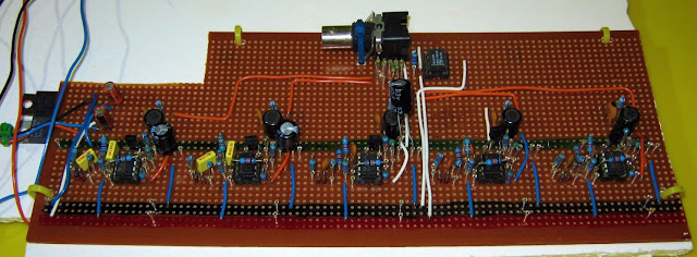
Frequency division multiplexing (FDM) was used to transmit all of the data over a single cable.  The five similar sub-circuits at the bottom of the image below contain an oscillator and a mixer.  The oscillator generates a carrier signal, while the mixer modulates the carrier with a signal from one of the sensors that are powered by the FDM board.   An op-amp summing circuit then combines the modulated carriers into one signal.  Some parts have not been soldered to the board, instead they are connected via round header pins.  This allows specific parameters such as oscillation frequency to be changed.
Polysomnography Prototype
Frequency Division Multiplexing Board

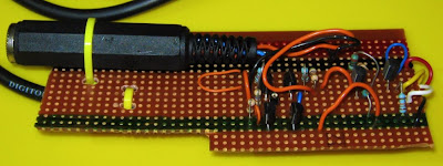
The next board is nothing spectacular.  It's just a pre-amplifier for the microphone that is used to record snoring sounds.
Polysomnography Sensor
Microphone Pre-amplifier Board

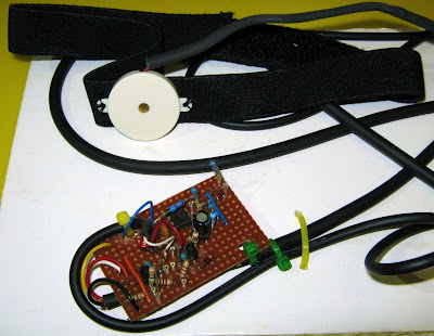
The next board is almost the same as the last, it's just a pre-amplifier for a piezo electric sensor used to detect throat vibration.  The sensor is held in place against the throat using a velcro strap.  A slight choking hazard but this was only a prototype.
Polysomnography Sensor
Throat Vibration Sensor

A face mask from an asthma machine was used to make a breathing sensor.  The mask was slightly altered to make sure all the air flowed past a thermistor when breathing in and out.  As the air passing the sensor is hotter when a person is breathing out you can easily see the breathing pattern of the patient.  A simple circuit was then used to convert the resistance of the thermistor to a voltage.

The initial result wasn't spectacular due to the thermal response of the thermistor.  To improve the performance the outer coating of the thermistor was sanded off to make it more responsive.  Probably not the safest move, but you do what you can with what you've got.

Polysomnography Sensor
Breathing Sensor

The ECG board uses an instrumentation amplifier to improve common mode rejection while sensing the hearts electrical impulse.  A last minute change required a hacked up daughter board containing the instrumentation amplifier to be inserted into the socket of the old IC.  After the instrumentation amplifier a couple stages of filtering and amplification.  Finally and most importantly is an optical isolation stage.  This stage is needed for safety.  Because the probes of the ECG are connected to a patient, direct paths to main power need to be eliminated.  By powering the amplification stage from a battery and isolating it from the main board, the risk of shocking the patient is significantly reduced.

Polysomnography Sensor
ECG board

These are the ECG leads that were built.  They were the most professional looking part of the project.  Some audio cable, alligator clips, RCA plugs and a bit of heatshrink and you can do wonders.  The alligator clips can clip onto the snaps on the back of ECG pads, however, in the product demonstration the alligator clips were attached to dollar coins and taped to the skin.  Strategically shaving small areas makes removing the tape a lot easier.
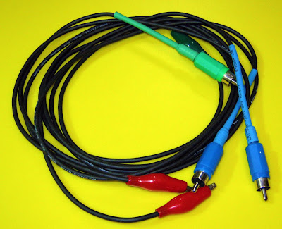
ECG Leads
DIY Test Leads

The most interesting thing about this project was how it made technology that seemed so complicated accessible.  An ECG machine seems like something that would cost thousands of dollars to build, and it does if you want something good, but with a few basic parts you can hack something together for under 50 bucks.

Another interesting thing I learned from this project that's unique to this situation is that you can't hold your cards close to you chest when wearing a heart monitor.  When doing a demonstration in front of your professor and he can see that your heart rate is 120 bpm, he has a fair idea you're terrified.