Monday, April 29, 2013

Homemade Surface Mount Vacuum Pick-Up Tool

Lately I've been experimenting with surface mount components, trying to better understand how to design for them, how to solder them, and how to place them.  I'm getting better at designing for them and understanding the different soldering methods, but I still have issues placing parts on PCBs.  Using tweezers is okay, but I wanted to see if I got better results using a vacuum pick-up tool.  After all, industrial pick and place machines use a vacuum to lift components, why can't I.  So with that in mind, I decided to build my own, hopefully learning the idiosyncrasies of the process during the build.

Brass hand-piece
Home made vacuum pick-up tool
My design was reasonably basic with only a few requirements.  The vacuum pump needed to be controlled by foot, freeing up my hands to place parts.  Ideally the hand-piece should be about the same size as a pen to make it ergonomic to use.  Finally the hand-piece should be fitted with a luer-lock connector to allow tips to be easily changed.  The rest of the design wasn't too important and was dictated mainly by what parts I could get my hands on.  After an initial failed attempt I'm happy with the results, both aesthetically and functionally.

vacuum pick-up tool setup
Hand-piece with power supply, foot switch, and vacuum pump
A quick demonstration of the system's capabilities


The Build

A couple items necessary for the build were a foot switch and a vacuum pump.  The easiest way to get these was to order them through Little Bird Electronics.

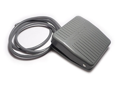
The foot switch was sourced from Seeed Studios and would easily do the job.  It's rated for 10 A at 250 V and has NC/NO contacts.  The colour coded wires on my switch were wrong, so it pays to double check the wiring with a multi-meter first.
foot switch
Foot Switch - Image from seeed studio
The vacuum pump was sourced from SparkFun Electronics and is capable of a vacuum of 16 inches of mercury which is about half an atmosphere.  Ideally if there aren't any leaks the flow rate shouldn't matter as there will be almost no air flowing when parts are attached to the tool.  The pump requires a 12 V, 1 A power source which is supplied by a switch mode wall-wart that was surplus from another project.

Half an atmosphere is more than enough to lift surface mount components.  In a perfect demonstration of the Square cube law, as the parts being lifted shrink, their mass shrinks by the cube of the scaling factor, while the area available for lifting shrinks by only the square of the scaling factor. For example, if the dimensions of a part are halved, it now weighs an eighth as much and has a quarter of the area to lift it.  This means that ideally you would only need half the vacuum pressure to lift it.  This means the vacuum pressure to lift components decreases as the parts get smaller.

vacuum pump
Vacuum Pump - Image from sparkfun.com used under a CC BY-NC-SA 3.0 license
A simple cable harness was built to connect the foot switch, power supply, and vacuum pump.

With the main components sorted, all that was left was the hand piece.  After thinking it over for a while I decided to use brass.  It should be strong, but easy enough to work with and join.  It did require me to buy a MAPP blow torch to silver solder all the parts together, but you can never have too many tools.  I also had a fun couple of days figuring out how to solder, only burnt myself once too.

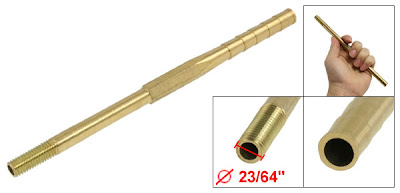
I didn't have access to a lathe or a suitable size of brass tubing, so I had to work with what I could find.  I came across the injection moulded brass body piece shown below on ebay.  I have no idea what it does or what it's for, but it was something I could work with.  I started by cutting the pipe to length by removing the thread on the end.
Brass Pipe
Brass body
Brass Pipe
Brass body without thread
The barbed fitting on the end of the pipe was too large for the 1/4 inch ID tubing I had to fit the vacuum pump.  This meant that another fitting needed to be added to the pipe to connect to the smaller tubing.  The thread was cut off a barbed fitting similar to the one below and the barb soldered to the body of the hand-piece.

brass fitting
Barbed fiting
soldered joint
The barbed fitting soldered to the main body
In the close up of the soldered joint below you can see that it's a bit messy.  Silver solder apparently works best when joining two closely fitting metal pieces, it isn't ideal for filling.  I think If I had another go I could do a better job, but after a clean it'll look fine.

soldered joint
The soldered joint
The next step was quite nerve racking.  Up until now the parts used were cheap and easily replaceable, the next part wasn't.  The tiny luer lock connector to be fitted to the tip of the hand-piece cost forty dollars (you can get them cheaper overseas, everything costs more in Australia), and because I'd melted some test pieces when practising soldering I was a little hesitant.
brass fitting
Luer lock connector to hold vacuum tips
Before soldering, the edges of the the two parts were bevelled to make a stronger joint.  I'm not sure if it was required, but it seemed like a good idea.  The nickel plating on the fitting was also removed where it was going to be soldered.

brass fitting
Bevelled fittings before soldering
I bit the bullet and soldered the luer connector to the main body and everything turned out perfectly.  The solder was sucked into the joint and ran all the way around to make a beautiful joint.  After a little filing you can see the result below.  The grip on the luer connector was also sanded off to make the tool more comfortable to use.

Although the hand piece will accept any luer fitting, it's preferable to use a metal one.  If a plastic fitting was used, the air flow through the tip could cause a static charge to build up on the plastic and discharge into the part being lifted damaging it.  If a metal fitting is used, static build-up can be controlled.

Now for some tests.

vacuum pick-up tool
Metal Tip fitted to the hand-piece
vacuum pick-up tool
Vacuum tip lifting an MSOP-8 package
I know I said metal tips were preferred, but I have a set of plastic ones that I'm using to understand what size tip is needed to lift what package.

vacuum pick-up tool
21 gauge blunt tip bent needle fitted
vacuum pick-up tool
22 gauge vacuum tip lifting an 0603 resistor (1.6 x 0.8 mm)
The rubber suction cup in the images below was from a cheap pickup tool I bought onilne, so I serious doubt it's an ESD dissipative rubber, but they can be bought and when used with a metal tip would create an ESD safe tool.

vacuum pick-up tool
14 gauge vacuum tip with a rubber suction cup attached
vacuum pick-up tool
Suction cup lifting a PCB
To securely connect the tubing to the hand-piece an ear clamp was used.  I'm not sure what the tool was that I used to crimp the lugs.  From what I understand, it might be a fencing tool.  Edit:  I've now learnt they are called pincers.

crimping tool
Ear clamp with the tool used to crimp the lugs
I was happy with how things turned out, but the hand-piece needed something more.  It was just crying out to be polished.  It was rubbed down with 800 grit wet or dry sandpaper.  The curved parts were done by cutting strips of sandpaper and wrapping them around the hand-piece.  To finish it off it was rubbed down with steel wool and then rubbed with Brasso.  There are still a couple of fine scratches that I could get out with a finer grade of sandpaper, but I'm satisfied with the end result.

Brass hand-piece body
After a quick polish
Brass hand-piece body
After a quick polish
Overall things worked out well,  but I still have to tweak the design a little.  When the foot switch is released the vacuum isn't released straight away, which means the parts don't come off the vacuum tip for sometimes 40 seconds.  Ultimately it means I did too good of a job making sure there were no leaks.  I just assumed that the vacuum would release through the pump, but it seals tight when power is removed.  Reducing the length of the tubing would also help as it acts as a large vacuum reservoir.

I enjoyed this project. I made something I'm proud of, got to practice silver soldering, and made a tool that's usable and just what I want.

Thursday, April 18, 2013

Logging and Graphing Ping from the Linux Command Line

Lately I've been having a bit of trouble with my ISP.  For the past month or so, between the hours of about 6pm and midnight I can't connect to Twitter.  The start and stop time of the problem varies, and it only occurs intermittently.  Some nights are fine and you think things are fixed, then it starts over again.  I thought it was me at first, but this thread over at Whirlpool shows a growing list of frustrated users with the same problem.  I though TPG would've been able to find the problem straight away, but I was wrong.

The TPG representative on the forum listed some tests that he'd like us to perform to help track down the problem.  Ideally doing tests like ping, traceroute, and nslookup before and after the problem starts.  I don't know much about the infrastructure of the internet or how routing occurs, but I'm familiar with these commands and what they mean.  I'd like to help out, but because the problem was intermittent I kept missing the right time to run the tests, and after a week or so of trying I was fed up.

I had an ancient laptop sitting beside me running an outdated version of Ubuntu that I decided to put to use.  By automating the process of running the tests and logging the output I would be able to capture the exact moment of failure and hopefully pinpoint the problem.  After all, the internet without Twitter just isn't the same.

Recording the result of the tests was easy, a quick and dirty bash script did the job.


logger.sh

#!/bin/bash

DATE=$(date +%Y_%m_%e_%H_%M_%S).log    #get date YYYY_MM_DD_HH_MM_SS

printf "ping -c 5 twitter.com \n\n" > PING_twitter_com_$DATE
printf "%s\n" "$(ping -c 5 twitter.com)" >> PING_twitter_com_$DATE
printf "\n\n\n" >> PING_twitter_com_$DATE

echo $DATE

The script is simple.  It gets the date in a human readable sortable format writes the command to run as a string to a file named PING_twitter_com_YYYY_MM_DD_HH_MM_SS.log.  It then writes the result of the command to the file.  More tests can be added by replicating the above code for each command.  By issuing the following command

while true; do ./logger.sh; sleep 300; done;

logger.sh will be run every 5 minutes (actually it's every 5 minutes plus the time to run the tests) until stopped.  This will generate a log file for each execution containing the data we want.  An example is below.

PING_twitter_com_2013_04_18_20_17_59.log

ping -c 5 twitter.com

PING twitter.com (199.59.148.10) 56(84) bytes of data.
64 bytes from twitter.com (199.59.148.10): icmp_req=1 ttl=51 time=256 ms
64 bytes from twitter.com (199.59.148.10): icmp_req=2 ttl=51 time=256 ms
64 bytes from twitter.com (199.59.148.10): icmp_req=3 ttl=51 time=257 ms
64 bytes from twitter.com (199.59.148.10): icmp_req=4 ttl=51 time=257 ms
64 bytes from twitter.com (199.59.148.10): icmp_req=5 ttl=51 time=257 ms

--- twitter.com ping statistics ---
5 packets transmitted, 5 received, 0% packet loss, time 4005ms
rtt min/avg/max/mdev = 256.601/257.101/257.432/0.464 ms

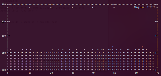
This is great, but it's a bit hard to see what's going on.  By extracting the average ping value and graphing it over time, a better picture of the problem can be created.  A command line graph can be generated from a directory of log files with the following command.

cat PING_twitter_com*.log | awk -F '[ /]' '/rtt/{ print $8 }' | gnuplot -persist -e "set terminal dumb 121 28; set yrange[200:400]; plot '-' with impulses title 'Ping (ms)';"

At first it seems a little complicated but once you break it down things become clear.  The required files are read with cat.  The files are read in order because the wild card operator used will guarantee that.  This is then piped to awk.  It looks for lines that match a pattern.  rtt is at the start of the lines that contain the average ping so I've set awk to look for that, but you could've used mdev or another string on the line you are looking for.  The field separators for awk are set with the dash F option to be space and forward slash.  This makes extracting the average ping easy.  By breaking the line up at spaces and forward slashes you can see that the average ping is the eighth field.  awk is set to print the eighth field as its output.  This is piped to gnuplot.

gnuplot needs to be set to use the terminal.  The "set terminal dumb" command does this.  Plotting the data from stdin is done with the plot '-' command.  This gives the basic info, but is can be spruced up a bit with some extra formatting, ie, changing the range, using impulses, enlarging the graph, and giving the data a title.  It's up to you to decide what looks best.

Linux Command Line Graph
A graph of ping results to twitter.com every 5 minutes

As you can see from the graph above, I didn't encounter the problem tonight.  The average ping result remained remarkably stable at around 250 ms.  Who knows, they may have fixed the problem.  But i'll run this for the next couple of nights just to make sure.


Sunday, April 7, 2013

Trying to Strip Nickel Plating From Brass Fittings

The fitting that I plan to use in my vacuum pick-up tool arrived the other day, so now I can get started on making a handle for it.  The fitting is a nickel plated brass male Luer lock to 1/4" - 28 UNF thread connector.
Luer Lock Fitting
1/4 - 28 UNF thread
Luer Lock Fitting
Male Luer lock thread
Luer Lock Fitting
Luer lock fitting
My plan is to attach the fitting to the hand piece in the image below.  I can cut the brass piece to the size I want and then connect the Luer fitting to it.  To make sure the fitting is secure and has no chance of coming undone I've decided to braze it in place.  To do this I need to strip the nickel coating off the brass Luer fitting.  I think you can braze nickel plating to brass parts, but I'm not familiar with it, and because the Luer fitting cost $40 I want to stick with what I know.  I should point out that I'm just going by trial and error here.  I just trying things and seeing what works.
Brass Pipe
Brass hand piece

My first attempt to take off the plating involved leaving the fitting soak in vinegar overnight.  I didn't think it would do anything, and as expected nothing happened, but it was worth a shot.
luer lock fitting
Fitting in Vinegar
Next up I decided to try electrolysis to strip the plating.  I've had some experience with it in the past and am aware of things to watch out for.  I fed a wire through the fitting and flared the end of the wire.  By pulling this back, the threaded end of the fitting could be suspended in the electrolyte without the rest of the object being submerged.
luer lock fitting
Electrical connection to fitting
I used the vinegar from the first part of the experiment with some salt in it as the electrolyte.  There was likely to be some pitting, but since I'm not interested in the thread, it doesn't matter if it's slightly damaged.  A small current from a lab power supply was applied to the apparatus for several hours to perform the electrolysis.

The results weren't that great.  The coating was being stripped unevenly, with some parts disappearing quickly while others were left untouched.  One unexpected result was that the surface of the metal started to take on the salmon pink colour of copper.  To me, this indicates that the zinc from the brass was being removed leaving the copper behind.  Did not expect that.
luer lock fitting
Fitting undergoing electrolysis
After my first couple of attempts didn't work too well I decided to use some elbow grease and got to work with a small file and some steel wool.  As you can see in the images below, the thread and the flat part below it have taken on the familiar yellow colour of brass.  I may need to make some further modifications but until the hand piece I ordered turns up I can't really be certain.
luer lock fitting
Fitting with brass exposed
luer lock fitting
Fitting with brass exposed